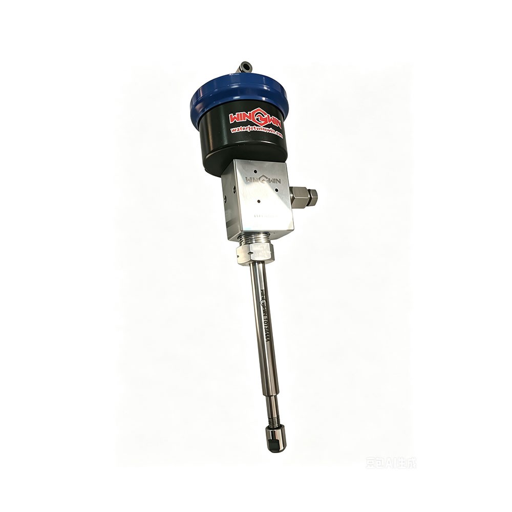
Product number: 10178168, 10178184
Product name: Pneumatic Valve, Water only, HP, Cutting head Assembly, 3/8 Nozzle Nut, 60K, 3AXIS cutting head, pure waterjet cutting head.
Introduction to the 10178168 10178184 Waterjet Cutting Head for KMT:
1. Names of the components of the waterjet cutting head assembly:

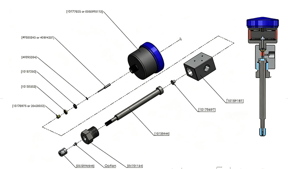
| No. | Product number | Product name |
| 1 | 10177855 | Actuator Assembly, HP, Normally Closed, 60K |
2 | 49865843/49894207 | Valve stem |
| 49895584 | O-ring | |
| 10187250 | Ring, Back-Up, SST, HP, 60K, | |
| 10188233 | Ring, Back-Up, Brass, HP, 60K | |
| 3 | 10178978/20428052 | Seal assembly |
| 4 | 10189181 | Valve body |
| 5 | 10178697 | Seat, Pneumatic Valve, HP, UHP, 60K, 90K, |
| 6 | 10138444 | Nozzle Tube, 3/8 Nozzle Nut Connection |
| 7 | BV701184 | Gland, Nozzle Tube, .562 ID, 60K, 90K |
| 8 | B2841 | Nozzle Nut, .38, HP, 60K |
2. The purpose of this 10178168 10178184 Waterjet Cutting Head:
1. 10178168 10178184 Waterjet Cutting Head is a high-performance replacement solution designed waterjet cutting systems and other compatible waterjet cutting machines. It is ideal for replacing worn or damaged original cutting head assemblies, helping restore cutting accuracy, stable pressure, and reliable performance while reducing maintenance downtime.
2. This waterjet cutting head assembly is also widely used for machine upgrades and retrofits. It allows users to convert other brands of water jet cutting equipment to a reliable KMT-style waterjet cutting head, making maintenance easier and replacement parts more accessible. In addition, abrasive waterjet systems can be modified into pure waterjet cutting applications for industries such as food processing, paper, foam, rubber, textiles, plastic, and other soft materials where abrasive is not required.
3. The assembly is also an excellent choice for adding an extra cutting station to increase production capacity or integrating into custom automation and OEM waterjet equipment. Compatible with waterjet parts, waterjet cutting head replacement, pure water cutting head, waterjet nozzle assembly, and high pressure waterjet cutting applications, the 10178168 / 10178184 Waterjet Cutting Head provides an economical, dependable solution for repair, upgrade, expansion, and new machine installation.
3. Installation instructions for the internal valve seal and repair kit 05116025 of this waterjet cutting head:
Please see the video link below for instructions.
https://www.youtube.com/shorts/fO8zHO4NXzU
The detailed analysis steps are as follows of the repair kit from the waterjet cutting head :

Seal pushing tool 2. Seal installation tool 3. Seal positioning tool
Replacement and Installation Instructions of the repair kit from the waterjet cutting head:
1. Disconnect the air supply.
2. Disconnect the air supply hose and electrical wiring from the solenoid valve.
3. Loosen and disconnect the high-pressure sealing gland connector and the vent connector.
4. Remove the pneumatic control valve and its actuator assembly from the ultra-high-pressure water jet pump.
5. Loosen and remove the actuator.
6. Loosen the high-pressure connector and remove it, along with the high-pressure connector cone and valve seat.
7. Remove the valve stem, SST back-up ring, and brass back-up ring from the valve body.
8. Remove the sealing assembly by pushing it with a wooden, plastic, or brass lever. A seal pusher tool can also be used to remove the sealing assembly. The seal assembly should be pushed out through the actuator port on the top of the valve body.
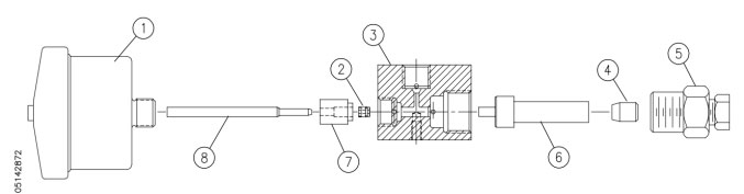
| No. | Product number | Product name |
| 1 | 10177855 | Actuator Assembly, HP, Normally Closed, 60K |
| 2 | 10178978/20428052 | Seal assembly |
| 3 | 10189181 | Valve body |
| 4 | Insert | |
| 5 | M/F adapter | |
| 6 | Seal positioning tool | |
| 7 | Seal installation tool | |
| 8 | Seal pushing tool |
9. Clean the valve body, taking care not to damage or scratch the bore.
10. If replacing the sealing assembly, first remove the brass wedge ring. Lubricate a new seal and O-ring with FML-2 food-grade grease. Insert the seal and O-ring into the seal installation tool, inserting it into the tapered end of the first seal.
11. Place the seal positioning tool on the opposite end of the valve body and secure it using a high-pressure connector. Once the seal is positioned, place the seal installation tool into the mating cavity of the valve body.
12. Secure the positioning tool and use the seal pushing tool to push the bore of the valve body until the shoulder of the pushing tool contacts the seal installation tool.
13. Remove the pushing tool, installation tool, and positioning tool.
14. Place the brass wedge ring into the seal pushing tool (thick end first) and use this tool as a positioning reference to position the wedge ring into the seal. 15. Remove the push tool and gently move the wedge ring onto the seal with your fingertips.
16. Install the existing SST support ring and a new brass support ring onto a new valve stem. The "V" groove on the SST support ring should face the brass back-up ring. The smaller outer diameter of the brass back-up ring should face the sealing assembly. Refer to Figure 9-26 for pneumatic control valve components.
17. Insert the sealing assembly into the valve body, allowing the valve stem to enter the inner diameter of the sealing assembly.
18. Apply anti-jamming compound to the actuator threads and carefully screw the actuator onto the valve body, guiding the valve stem into the actuator bore. Rotate the actuator clockwise until resistance is felt. Rotate the actuator counterclockwise 1/4 turn and then quickly clockwise to seat it. 17. Tighten by hand only, with a tightening torque of 5 ft-lbs (7 Nm).
18. Apply anti-seize compound to all surfaces (except the inner diameter of the new valve seat). Install the valve seat onto the valve body, inserting the smaller outer diameter first.
19. Apply anti-seize compound to the threads of the high-pressure connector and to the back of the high-pressure connector. Position the tapered part of the high-pressure connector onto the high-pressure connector and install the high-pressure connector with a torque of 50 ft-lbs (68 Nm).
20. Replace the 1/4-inch drain clamp nut and collar with a torque of 25 ft-lbs (34 Nm). Seal the gland fitting with a torque of 50 ft-lbs (68 Nm).
21. Apply anti-seize compound to the threads of the 3/8-inch high-pressure sealing gland fitting. Install the collar and seal.
22. Install the air supply hose and electrical connector onto the solenoid valve. Open the air pressure to the actuator and check for leaks in the solenoid valve, and check if the solenoid valve is operating normally.
If you are interested in any waterjet products, or need any technical support, feel free to contact us please.
Contact: Linda Lyu
Phone: +86 15802487169
Tel: +86 15802487169
Email: info@waterjetsupplier.com
Add: Pacific Industrial City 67-32, Shenbei Dist, Shenyang, Liaoning 110001. P. R. China
We chat






 English